Designing for Printability — The Rules Nobody Told You
Most CAD models look correct in software and print badly. These are the reasons why.
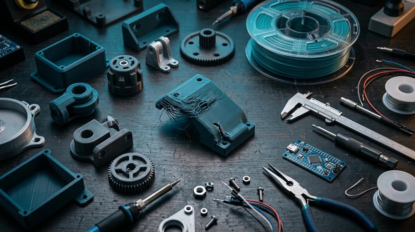
You designed it in Fusion 360. It looks perfect on screen. It came back from the printer with a sagging overhang where the cable routing goes, holes that are 0.4mm too tight, and a wall that split right at the mounting point. None of this showed up in the preview.
FDM 3D printing has specific constraints that don't exist in machining or injection moulding. Knowing them before you design saves you two or three print iterations.
Overhangs: the 45-degree rule
FDM prints layer by layer from the bottom up. Each layer has to be supported by the one below it. If a feature extends horizontally into empty air at more than about 45 degrees from vertical, there's nothing below it to support the freshly extruded plastic — it sags.
The fix is either to orient the part so overhangs are minimised, add support material (which has to be removed later, leaving a rougher surface), or redesign the overhanging feature with a self-supporting angle.
Practical example: a cable routing hole in the side of an enclosure. If it's circular, the top of the circle is a 90-degree overhang — it'll droop. Change it to a teardrop shape (flat bottom, pointed top) and it prints cleanly with no support needed.
Holes: always design them 0.2–0.4mm larger than you need
Printed holes come out slightly smaller than designed. The reason is that the extruded line has a finite width and the inside edge of a circle gets a tiny bit of extra material deposited on it. A 3mm hole in your CAD file reliably prints as a 2.7mm hole.
For clearance holes (where a bolt passes through), design 0.3–0.4mm larger than the bolt. For press-fit features (where a shaft or pin is meant to be gripped), test with a small print of just the hole before committing to the full part.
Wall thickness: below 1.2mm is risky
Standard FDM nozzles are 0.4mm wide. The slicer lays down walls in multiples of the extrusion width. A wall designed at 0.8mm might print as a single extrusion that's mechanically weak. A wall at 1.2mm is 3 extrusions wide and significantly stronger.
For load-bearing features — mounting bosses, snap-fit clips, hinge pins — keep walls at 2mm or above. For cosmetic enclosures with no structural load, 1.5mm works fine. Anything below 1mm is likely to print poorly or not at all.
- Overhangs beyond 45°: add support or redesign geometry.
- Holes: add 0.3mm to diameter for clearance fits.
- Walls: minimum 1.2mm, structural features 2mm+.
- Bridges: spans up to about 50mm print without support; beyond that, expect sag.
- Text: embossed text at 0.5mm depth or above, minimum 4pt font size.
"I redesigned the same enclosure four times before I understood the 45-degree rule. Would have saved a week if someone had told me on day one." — electronics student, Bangalore
Orientation matters more than most people realise
How you orient a part on the print bed affects everything: surface finish, strength, support requirements, and print time. FDM parts are weakest along the Z axis (between layers), so load-bearing joints should align with the XY plane.
For a simple enclosure: print with the open face down (facing the bed). This puts the most critical surfaces — the ones that mate with other parts — in the XY plane where they're most accurate, and eliminates the overhang inside the enclosure cavity.
Bridging: how far can you span without support?
Bridging is the ability to print horizontally across an air gap between two supported walls. PLA can reliably bridge up to about 50mm with minimal sag. Beyond that, you'll see drooping on the underside of the bridge — not a structural failure, but cosmetically imperfect and potentially interfering with tolerances.
For electronics enclosures, internal cable routing and connector cutouts often involve bridges. Keep horizontal spans under 40mm if you want clean undersides. Wider openings should have a support structure or be redesigned as two separate pieces joined after printing.
File review catches these issues before printing
RoboDIB's Bangalore print service checks geometry before the job runs. Problematic overhangs and thin walls are flagged before material is wasted.
None of these rules are hard. They just aren't obvious from within a CAD tool. Learn them once, apply them from the start, and your first prints will look like fourth-iteration prints.
More from the blog
RoboDIB
Solve these problems yourself
AI inventory, component map, 3D printing, and circuit design tools — all built for India's maker community.