Designing 3D-Printed Enclosures for Robotics Projects — What Actually Works
An enclosure that looks good on screen but fails on the bench is worse than no enclosure at all.
The gap between a 3D model that looks right and a 3D printed part that works right is where most robotics enclosure projects fail. I've made all the classic mistakes — interference on connectors that looked fine in the model, walls that cracked because they were too thin for the material, screw posts that stripped on first assembly.
After enough iterations, the failures teach you a design language specific to FDM printing. Here's what I've learned.
The Layer Line Direction Problem
FDM prints are anisotropic — they're strongest along the layer and weakest between layers. For an enclosure, this means you need to think about where stress is applied and how the print is oriented.
A tall thin post printed vertically (layers stacked along its length) is much weaker than the same post printed horizontally (layers going across its cross-section). If your design has posts or tabs that will experience bending stress, orient the print so layers run perpendicular to the expected load direction.
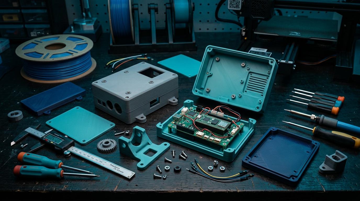
- Screw bosses: print vertically, with layers going across the boss cross-section
- Snap tabs: orient so layers run perpendicular to the snap direction
- Lid hinges: align layer lines with the hinge axis, not against it
- Thin walls: minimum 1.2mm for two-perimeter walls; 2mm+ for structural walls
Tolerance and Fit
This is where most beginners burn themselves. If you want a board to slide in cleanly, design the slot to be exactly the board dimensions — it won't fit. FDM prints have dimensional variance of ±0.3–0.5mm in X/Y, more in Z.
For sliding fits (a board in a slot), add 0.4–0.6mm clearance per dimension. For press fits (a bolt in a hole), you want negative clearance — holes should be 0.1–0.2mm smaller than the nominal diameter of the bolt. Test with a tolerance test print before committing to a full enclosure.
Model everything to nominal dimensions first. Then add tolerance offsets as a final design step, not as you go.
Heat Management in Indian Conditions
This is underappreciated. Bangalore is moderate, but leave a PLA enclosure in direct sunlight or in an enclosed space in summer and it will warp or soften. For anything that will live outdoors, in a vehicle, or near heat-generating electronics, use PETG or ASA.
Ventilation holes in enclosures aren't just aesthetic — they meaningfully reduce internal temperature for enclosed electronics. Add them to any enclosure that will run continuously. Size them so you can add a small filter foam to keep dust out.
Assembly Hardware
M3 heat-set inserts are the right way to do threaded connections in 3D-printed enclosures. Pressing them in with a soldering iron creates a durable connection that can be assembled and disassembled many times. Self-tapping into printed plastic works for light-duty use but strips eventually.
Get your enclosure printed right
Upload your STL and specify the material. We print in PLA, PETG, ABS, and more — right in Bangalore.
More from the blog
RoboDIB
Solve these problems yourself
AI inventory, component map, 3D printing, and circuit design tools — all built for India's maker community.