Building a Line Follower From Scratch — Everything You Need to Know
Line followers are a gateway project into real robotics. Here's a complete guide from sensor placement to PID tuning
Line followers are the 'Hello World' of robotics competitions. Simple concept: follow a black line on white surface. But a robot that actually follows a line well — at speed, through curves, across intersections — is an exercise in sensor design, control theory, and real-time programming.
This guide covers a sensor-to-motor loop that works. Not just enough to limp around a course, but fast and reliable.
Sensor Array Design
IR sensors (TCRT5000 or similar) work by measuring reflectance. The line absorbs IR, the surface reflects it. Most beginner builds use 3–5 sensors. Competition builds use 7–9. More sensors = more position resolution = smoother control. Key: sensors should be spaced so adjacent sensors straddle the line width. For a 1.5cm line, 1.5cm spacing works well.
Error Calculation
With multiple sensors, assign weights: for a 5-sensor array, sensors are -2, -1, 0, 1, 2. When sensors read reflectance values, calculate weighted average position. If sensor values are [1, 0.8, 0.2, 0, 0] (normalized), the error is approximately -1.3 — the robot is significantly right of center. This continuous error signal is what feeds your PID.
PID Controller — The Core
P (proportional): correction proportional to current error. The bigger the error, the harder you steer. I (integral): accumulates past error — corrects steady-state drift. D (derivative): responds to rate of change of error — dampens oscillation. For most line followers, PD is enough. Adding I can help on curves but introduces instability if tuned wrong.
- Start with P only. Set I and D to zero.
- Increase P until the robot follows the line but oscillates side-to-side
- Increase D until oscillation dampens but response stays crisp
- If there's steady-state offset on straight sections, add small I
Motor Drivers and Speed
L298N works but wastes power as heat. DRV8833 or TB6612FNG are more efficient choices for competition bots. Use PWM frequency of 20kHz+ to avoid audible whine. Higher base speed amplifies PID effect — once the algorithm works at 40% speed, tune again at 70%.
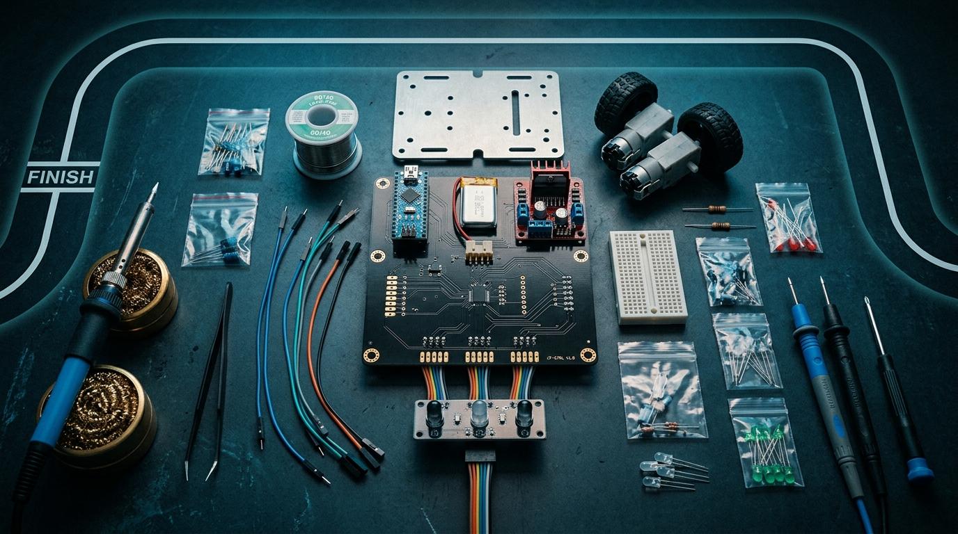
The Parts You'll Need
- Microcontroller: Arduino Nano or ESP32 (ESP32 has faster ADC)
- IR sensor array or TCRT5000 individual sensors
- Motor driver: DRV8833 or TB6612FNG
- 2x DC gear motors (6V, 200–300 RPM for chassis size)
- LiPo or 4x AA battery pack
- Chassis (3D printed or purchased)
Building a line follower for a competition?
Find IR sensors, motor drivers, and microcontrollers from makers near you.
More from the blog
RoboDIB
Solve these problems yourself
AI inventory, component map, 3D printing, and circuit design tools — all built for India's maker community.